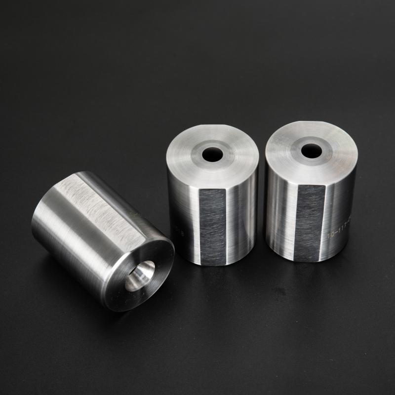
Inner Cutting Die: Definition, Characteristics, Applications, and Maintenance
1. Definition of Inner Cutting Die
An Inner Cutting Die is a precision tooling component used in manufacturing processes to cut, shape, or form materials from the interior of a workpiece. Unlike external dies that work on outer surfaces, Inner Cutting Dies operate within cavities or hollow sections, achieving high-tolerance features like holes, slots, or complex internal geometries. These dies are typically made from hardened tool steels (e.g., D2 with 60-62 HRC) or Tungsten Carbide (90-92 HRA) to withstand cyclic stresses. Their design incorporates cutting edges with rake angles between 5°-15° and clearance angles of 3°-8° to optimize chip evacuation and tool life.

2. Key Characteristics with Technical Data
Material Hardness: 58-64 HRC for steel dies, 88-93 HRA for carbide variants
Dimensional Tolerance: ±0.005mm for precision applications, ±0.02mm for standard industrial use
Surface Finish: Ra 0.2-0.4μm on cutting edges via precision grinding
Thermal Stability: Maintains dimensional accuracy up to 400°C (carbide versions to 800°C)
Fatigue Resistance: 500,000+ cycles at 200MPa stress amplitude (JIS G4401 SKD11 steel)
Cutting Edge Radius: 5-20μm depending on material thickness (thinner materials require sharper edges)
3. Primary Application Scenarios
Inner cutting dies serve critical functions across multiple industries:
3.1 Automotive Manufacturing
Used in producing fuel injector nozzles (diameter tolerance ±0.003mm), transmission valve bodies, and ABS component ports. High-speed servo presses (600-1,200 SPM) employ carbide inner dies for punching 0.5-3mm thick high-strength steels (HSS) with blanking forces up to 200kN.
3.2 Electronics Industry
Precision inner dies cut connector pin slots in PCB housings (0.1-0.3mm brass/phosphor bronze) with positional accuracy of ±0.01mm. Progressive die sets incorporate inner cutting stations achieving 0.05mm pitch repeatability for micro-USB and SIM card contacts.
3.3 Aerospace Components
Titanium turbine blade cooling holes (0.3-1.2mm diameter) are machined using PVD-coated (TiAlN) inner dies at 20-50m/min cutting speeds. Dies maintain ±0.008mm roundness after 10,000 cycles in Inconel 718.
3.4 Medical Device Production
Stainless steel stent cutting requires sub-micron edge sharpness (Rz 0.8μm) with 316LVM medical-grade material. Inner rotary dies achieve 0.05mm kerf widths at 30,000 RPM with coolant filtration to 5μm purity.
4. Maintenance Procedures
4.1 Daily Maintenance
Cleaning: Remove metal particles using ultrasonic cleaners (40kHz, 30°C) with pH-neutral solutions
Inspection: Check edge condition with 10x-50x magnification, measure flank wear (VB ≤ 0.1mm)
Lubrication: Apply thin-film corrosion inhibitors (0.5-1μm) on non-cutting surfaces
4.2 Periodic Maintenance
Edge Reconditioning: Diamond grinding (400-800 grit wheels) restores edge geometry when wear exceeds 0.15mm
Dimensional Verification: CMM inspection every 50,000 cycles (critical dimensions ±0.003mm)
Coating Refresh: Reapply PVD coatings (2-4μm TiCN) after 200,000 cycles
4.3 Storage Protocols
Maintain 20-25°C, 40-50% RH in anti-static containers
Separate dies with polyethylene foam (shore A 30-40) to prevent edge contact
VCI (Vapor Corrosion Inhibitor) paper wrapping for long-term storage
5. Failure Prevention Techniques
Thermal Monitoring: Infrared sensors detect abnormal temperature rises (>120°C) during operation
Force Analysis: Piezoelectric load cells monitor cutting forces (10-15% increase signals wear)
Microgeometry Control: White light interferometry verifies edge radius every 25,000 cycles
Stress Relief: Cryogenic treatment (-196°C for 24h) between regrinds extends tool life by 30-40%


